ASUS ROG Strix LC 240 AIO (white edition) unboxing and installation
Recently I decided to bite the bullet and replace my aging Prolimatech Megahalems Rev C. in its prime it was one of the best air coolers on the market. For some time I’d been eyeing off a decent AIO as whilst the Megahalems performs admirably even when paired with a Noctua NF-P12 Redux 1700RPM 120mm fan, I felt it wasn’t quite up to par for my use case. For those considering this cooler please note that it does not support Intel 12th Generation CPU’s unless your motherboard has LGA-1200 mounting holes (yes some LGA-1700 boards have LGA-1200 mounting holes). For those that don’t, you’ll need the LC II or another compatible cooler if you’re looking for an AIO compatible with Alder Lake.
In this article, I’ll unbox and install the ASUS Rog Strix LC 240mm on an LGA-1200 (10th Gen) Intel system. I’ll also cover compatibility in a good degree of detail.
If you get one of these please note that there were errata in my manual. It omitted to illustrate installing washers between the fan screws and the fans. There are sufficient washers supplied and omitting these will result in the screws hitting the fins on the radiator.
Note regarding terminology: I’ll use CPU block, Cold Plate, and pump fairly interchangeably as with other Asetek based AIO designs they’re all integrated into the one unit, and most commonly these will be installed on a CPU.
Unboxing, what’s inside?
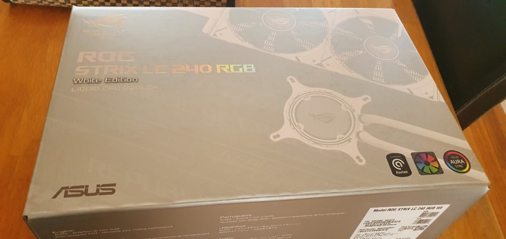
The box is quite nice with a hologram for the brand/model which is difficult to photograph, needless to say, it looks better in person.
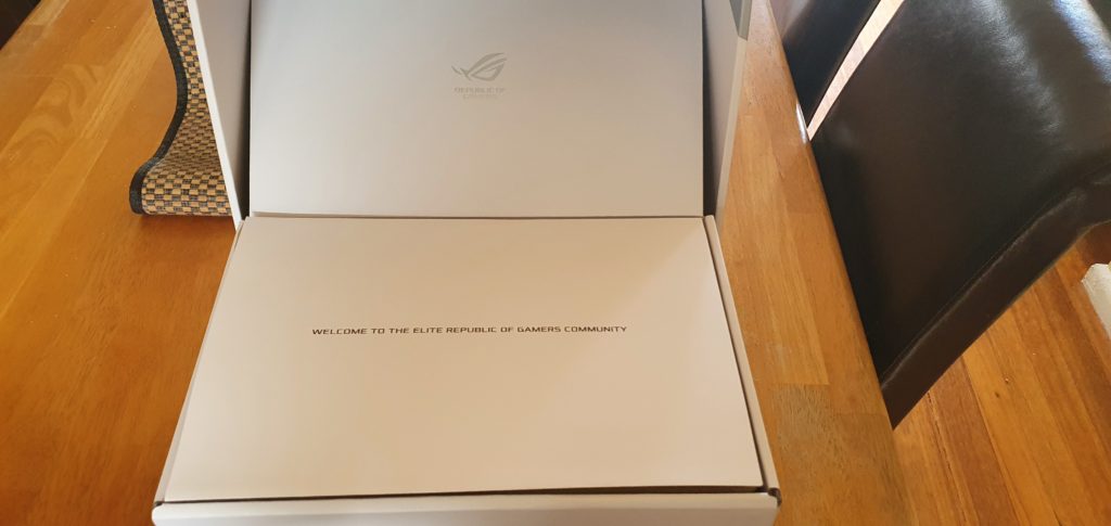
The box has a supporting piece of cardboard that prevents the lid from dropping shut whilst working, A nice little detail. The Welcome note is a nice touch, it’s backed with dense foam-like material.
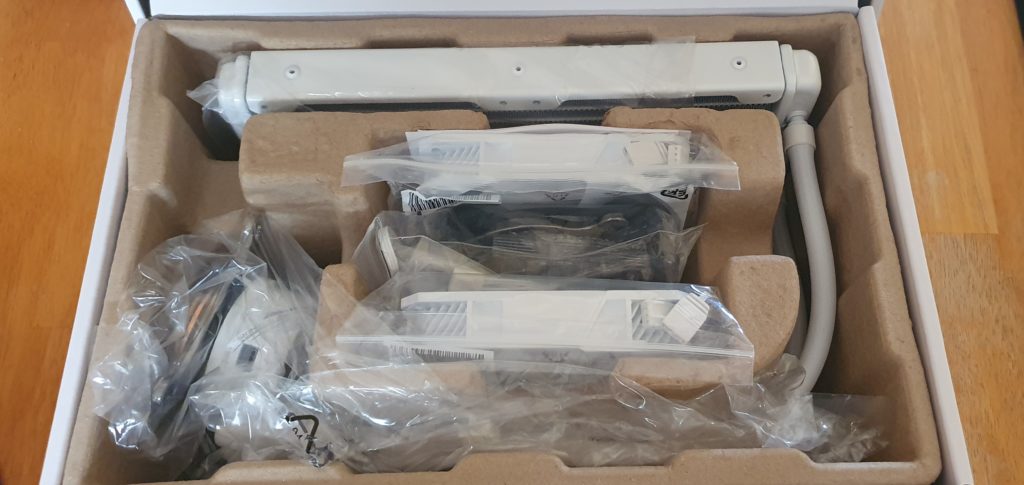
Inside the box, it’s all nice and securely packed.
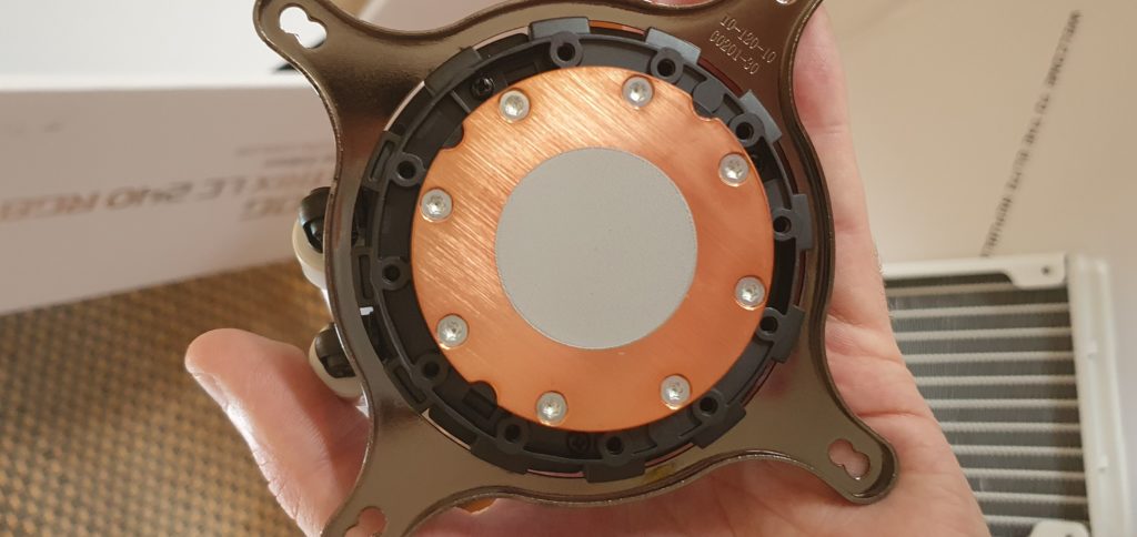
The cold plate (CPU block) has the thermal compound pre-applied, a plastic cover protects it prior to installation (not shown). Despite initially having some concerns (as one generally should with stock thermal compound) I found the pre-applied paste to be perfectly adequate. I did notice some odd sudden spikes in CPU temp immediately after installation which did catch my eye and make me think perhaps there was a mounting pressure, TIM issue, or an air bubble in an awkward place however the issue resolved itself overnight with no intervention and has been perfectly fine since. Whilst I suspect that better paste might get me marginal improvements in thermal performance I’m certainly in no rush to replace it.
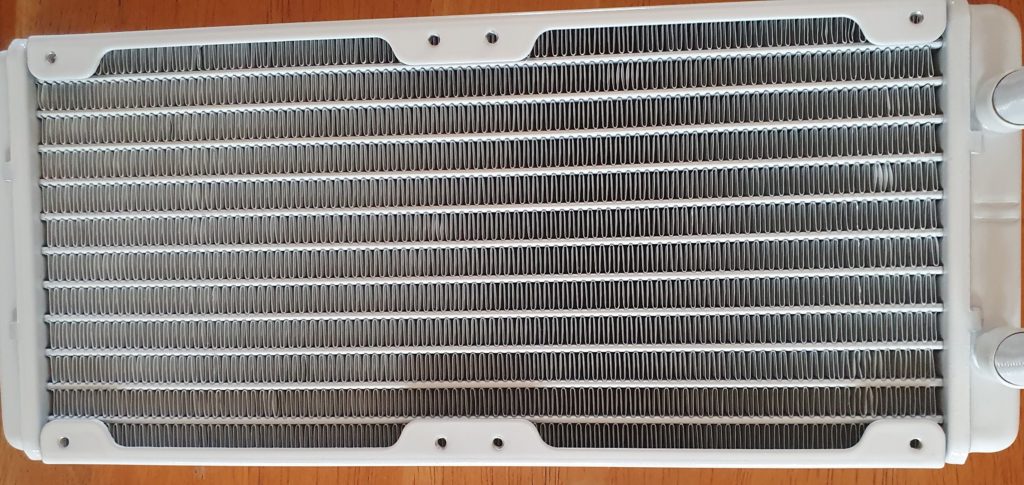
The radiator is as expected, it’s not unusual for the fins to not be perfectly uniform or to have a bit of a paint bubble on a fin. Both sides have a little of this. When installing these I avoid touching the fins or resting the radiator on things that may result in further damage. Thankfully the fans will obscure this side of the radiator and the case will partially obscure the other.
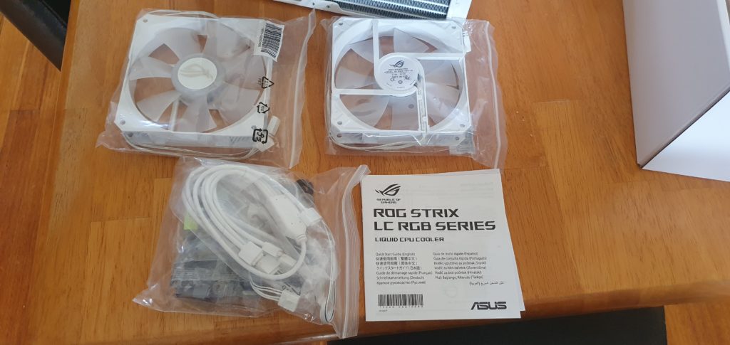
The two ARGB fans look great! ASUS includes a 4-way ARGB splitter, a 2-way 4 pin PWM splitter, and a 9 pin USB 2 to micro USB cable. I’ll detail all the requirements and compatibility for this cooler after the unboxing.
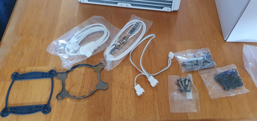
Personally, I found the AM4 bracket which I wasn’t using to be handy to keep the screws in one place, if you’re installing this on an AM4 platform replacing this ring on the AIO will be one of the first steps you take (in which case you’ll have an Intel bracket to do the same with :).
Will this cooler work for me?
I’ll break down each of these in more detail below but as a guide here’s a quick rundown of things you’ll want to check prior to purchase/install:
- A compatible CPU socket OR a motherboard which supports a compatible CPU socket (ie Intel 12th gen board with LGA-1200 mounting).
- A compatible case which can mount a 121 x 272 x 27 mm radiator with a fan that’s 25mm thick so a touch over 52mm clearance is required for the radiatiors thickness (as screws + washers protrude another 2-3mm). You will need sufficient room to allow a 380 mm long rubber tube to reach from the right side of the CPU to the radiator without excessive kinking (the cold plate barbs can swivel vertically up/down a little to aide in accomodating this).
- 2x 4 pin PWM headers (one for the pump one for the fans – these may be marked as pump or fan headers, generally it’s fine to use a fan header for an AIO pump)
“Optional” (for RGB lighting):
- 1x 3 pin (3 + 1 pin blanked/NC) 5v ARGB header
- 1x 9 pin USB 2 header ( 9 + 1 pin blanked), aka a USB 2.0 front panel connector, so make sure you’ve got a full spare 9 pin connector!
CPU socket support
The ROG Strix LC 240 RGB I purchased included both Intel and AMD mounting hardware it supports:
- Intel LGA
- 115x (1150, 1151, 1152, 1155, 1156)
- 1200
- 1366
- 20xx (2011, 2011-3, 2066)
- AMD PGA
- AM4
- TR4 (requres mounting bracket bundled with the CPU)
Note: As far as I can ascertain LGA-1700 specific brackets are NOT included with the original LC model so if you’re after a cooler for Alder Lake you might be out of luck. ASUS has released an LC II model which appears to have support, ASUS’ LGA-1700 support media release omits the ROG Strix LC 240 RGB however they do note that all ASUS Z690 boards include LGA 1200 mounting holes in addition to LGA 1700.
If you’re looking forward to AMD’s AM5 (LGA-1718) we’ll have to wait and see but early leaks indicate it’ll likely be compatible with AM4 solutions so you might be fine, however until release I’d say nothing is set in stone.
The pump and fans
Driving the pump + fans you’ll ideally need a pair of 4 pin PWM headers. The fans also support DC control mode so they should also work off of a 3 pin header. The pump probably would work off of a 3 pin header also but as it’s not mentioned in the spec sheets I can’t recommend it.
RGB Support
This particular cooler will require a 5v ARGB header for its lights to work. All required splitters are included, the cooler includes a 4-way splitter. You’ll only need two of these four for the AIO (one for each fan). In addition to a 5v ARGB header, you’ll also need a full 9 pin USB 2 header to drive and power the CPU blocks RGB.
Case compatibility and radiator orientation
When checking case compatibility generally looking if your case supports a 240mm radiator with a thickness of 52mm (including fans) in an appropriate orientation for an Asetek pump will suffice. If you’re not sure about mounting orientation please check out this excellent video that Steve from Gamers Nexus has made as it’s VERY important to understand if you value your AIO and your CPU’s health as many people install these incorrectly. These coolers use an Asetek pump and as such the pump is integrated with the cold plate. As a very rough guide, you do not want the cold plate (CPU block/pump) or the radiator barbs to be the highest point of the loop, but if you have any doubts please watch Steve’s video.
For more detailed requirements – you will need adjacent mounting holes or mounting rails for a pair of 120mm fans, the radiator measures 121 x 272 x 27 mm and the fans included are 120 x 120 x 25mm so you’ll need 52mm + the thickness of the screw heads + washers at an absolute minimum, however of course as this probably will be your air intake you’ll likely want a little more than this.
The tubes are 380mm long, you’ll want enough room for them to run from the right of your CPU to your radiator. The tubes are made of rubber so excessive bending will cause them to kink and inhibit performance, the cold plate barbs can swivel vertically to make this a touch easier.
Installing the ASUS ROG Strix LC 240 AIO
In this section, I’ll cover assembly, leak testing, removal of my preexisting cooler, and installation of the ASUS ROG Strix LC 240 AIO. I’ll assume you know how to safely work inside of a PC and take appropriate precautions to prevent damage from static electricity.
Assembling the ASUS ROG Strix LC 240 AIO
For the most part, this is pretty straightforward however I’ll cover it step by step. If you skip the manual please be sure to install washers between both the screws and fans and the screws and the case otherwise they may impact the fins on the radiator causing a small amount of damage (the manual’s illustration omits the washers on the fan side however you will have enough and it will prevent damaging the radiator).
Two other considerations when assembling these is that it’s best to avoid kinking the tubing if possible so give the cold plate plenty of room and try to avoid damaging the radiator fins. They’re not super fragile but they’re not particularly hardy either. I generally rest a radiator on a nice flat surface and never against anything except the case when I’m mounting it.
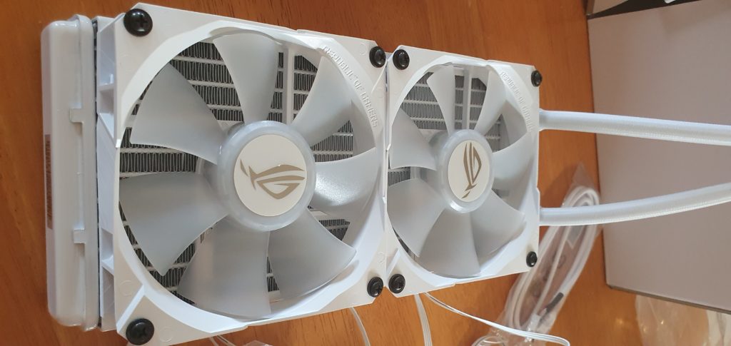
Installing the fans
Install the fans facing the correct direction, both for airflow and cable management, be sure to have the flatter side of the fan (the side which has the logo that doesn’t spin with the fan) facing the radiator and the spinny logo facing out as pictured below, as this will push air over the radiator which is generally the optimal configuration. When installing the fans use the long black screws, and as previously noted be sure to use washers as pictured below! The other consideration is to avoid under-tightening or over-tightening the fans, you want them firm so that you’ll not end up dropping a screw in your PC but not so firm that the fan’s plastic is bending noticeably.
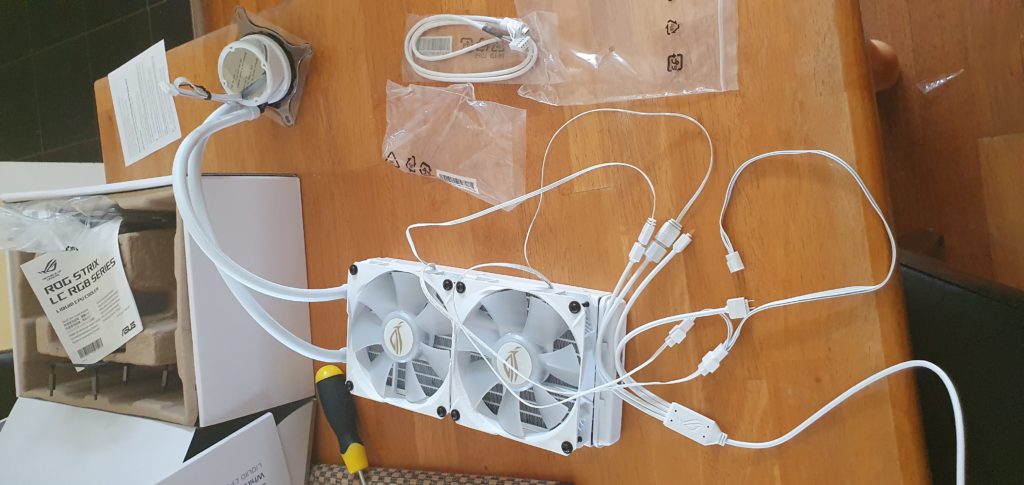
Attach the splitters
Once you’ve got both fans mounted it’s time to wire it all up. Separate the ARGB and the PWM cables then connect their respective splitters. The ARGB splitter has 4 outputs but we’ll only use two of them. The PWM cable only has two, one for each fan.
Once this is done it’ll look something like this, although at some point I managed to slightly tangle a cable but fixing that is as simple as unplugging the splitter and untangling, so no biggie.
It’s probably not a bad idea to attach the USB cable to the CPU block at this time. Be careful to not put your hand in the thermal paste when doing so (I left the plastic on till mounting the cold plate to avoid this but it’s easy to bump off). Be sure to check the orientation of the micro USB connector when doing (on mine the flat side of the connector faced up).
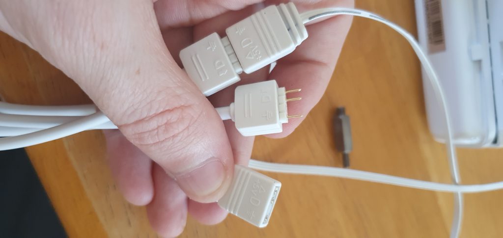
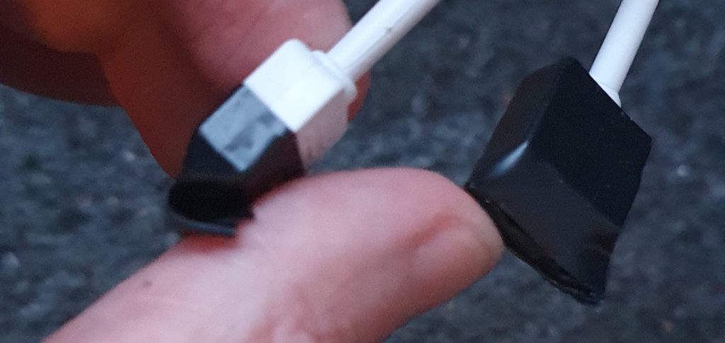
With the ARGB splitters, the manual suggests pulling the pins out. My attempt to do so failed miserably, I gave the pins a tug after what happened below but they were in there tight so I simply taped over them instead. If you end up in a situation like mine fear not. These little plastic bits usually simply slide back over the pins and a dab of glue is probably all that was holding it in place but it’ll be fine without it.
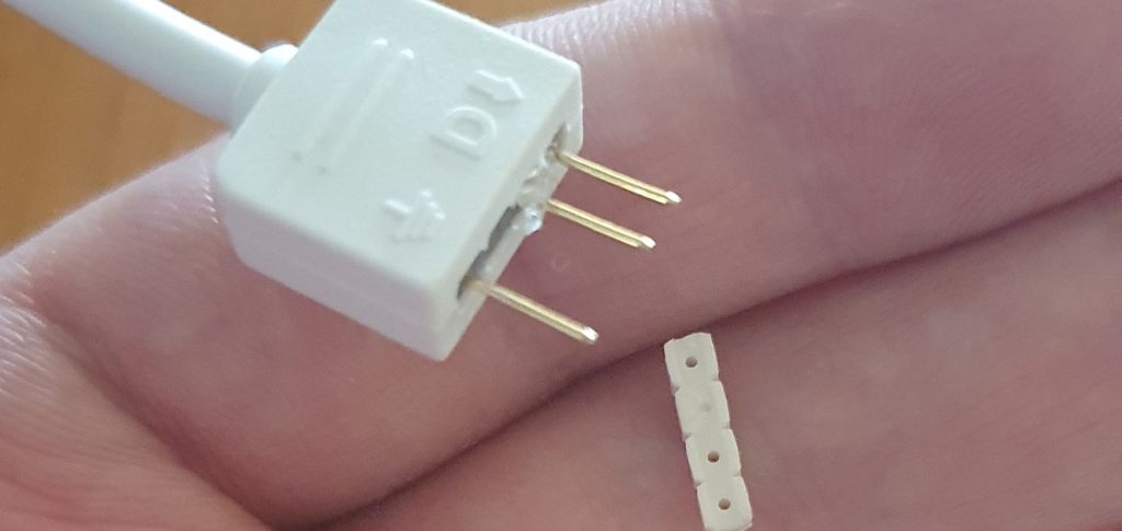
Don’t leave bare pins like these floating around your case, I simply used two small pieces of electrical tape, the picture below on the left is step one, I go around the connector once starting about halfway down, I then pinch flat the end of it and gently fold it over the pins as pictured on the left. I then take the second small piece of tape and go around the connector once more which will hold the flap in and keep the pins nicely protected and is nice and neat. With white tape, it would be barely noticeable.
If you’re using AM4
For AM4 you’ll need to switch the mounting bracket on the cold plate. Please check the manual for this procedure as I did not do it personally so I cannot make recommendations here. For Intel users, the appropriate mount is preinstalled.
Good work, if you’ve gotten this far then your AIO is now assembled and ready to leak test!
Leak testing
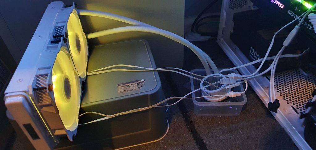
Whilst factories test AIO’s quite thoroughly it’s always possible that something has been harmed during transit or assembly so I always perform a leak test where possible outside of my PC. In this particular instance, cable length and header positioning made it a tad awkward so I started carefully with the case panel between the two then once I was happy it wasn’t going to spray liquid I dropped it in a tub and ran it for a couple of hours (with me watching Netflix and regularly checking it). Ideally, a proper leak test would be performed with a thermal load and further from the PC, but for many of us (myself included), I expect a setup comparable to the below image is the best we’ll be able to scrounge. Don’t worry too much about neat cabling here – the goal is safety and distance from the PC and it’s temporary.
As a minimum to test these you’ll need to plug in both 4 pin PWM connectors (the one coming off of the cold plate, and the one coming off of the 2-way splitter from the fans), once they’re plugged in, take note of which you plugged the cool plates connector into (I usually use a pump header or CPU_FAN header if a pump header is unavailable). I usually set that particular header to 100% via the BIOS and let it run for an hour or more. When testing, make sure the CPU block is below the radiator for Asetek setups like the ASUS Rog Strix LC 240. I also recommend testing the RGB side of things while you’re here (the 9 pin USB header + the 3 pin ARGB header) while you’re here as there’s nothing worse than fitting hardware and then realizing there’s a fault. Thankfully my cooler was in perfect condition so onwards with the installation!
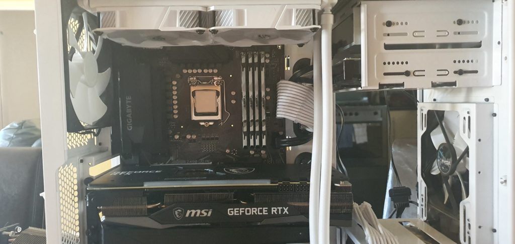
Removal of the existing cooler
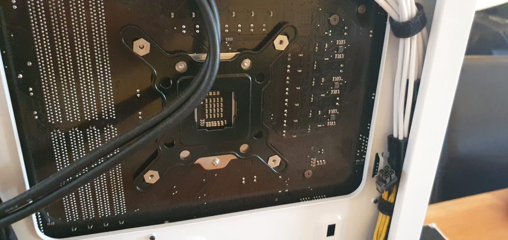
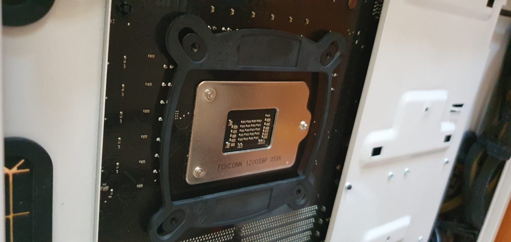
This will vary depending on the cooler you’ve installed. I suggest referring to your cooler’s manual. Generally speaking, you should be able to do this without removing the motherboard. In some instances, it’s helpful to remove the GPU so you have a little more room to work as it’s easy to accidentally rest on the GPU whilst unscrewing a big cooler. This is not great practice as it could damage the GPU or encourage sag. When you remove the cooler you’ll also likely want to remove the backplate as we’ll use the one from our AIO. Whilst this is under the motherboard it should be accessible in most cases as many have a gap underneath that point of the motherboard (see below – we want to remove the black star-shaped part that has the 4 threads sticking through the mounting holes, not the square-shaped silver part that it rests on as that belongs to the LGA socket). Some coolers (such as many stock Intel coolers) do not have a backplate.
After removing the cooler I recommend using some isopropyl alcohol and a fine cloth to remove any trace of thermal paste from your CPU IHS (Integrated Heat Spreader – the silver bit on top that contacts the cooler). Sometimes this is easier (particularly with LGA) if the CPU is removed. I recommend also cleaning up your old heatsink so that it doesn’t make a mess when being stored. I usually also assemble them for storage so that it’s difficult/impossible to lose any of the mounting hardware.
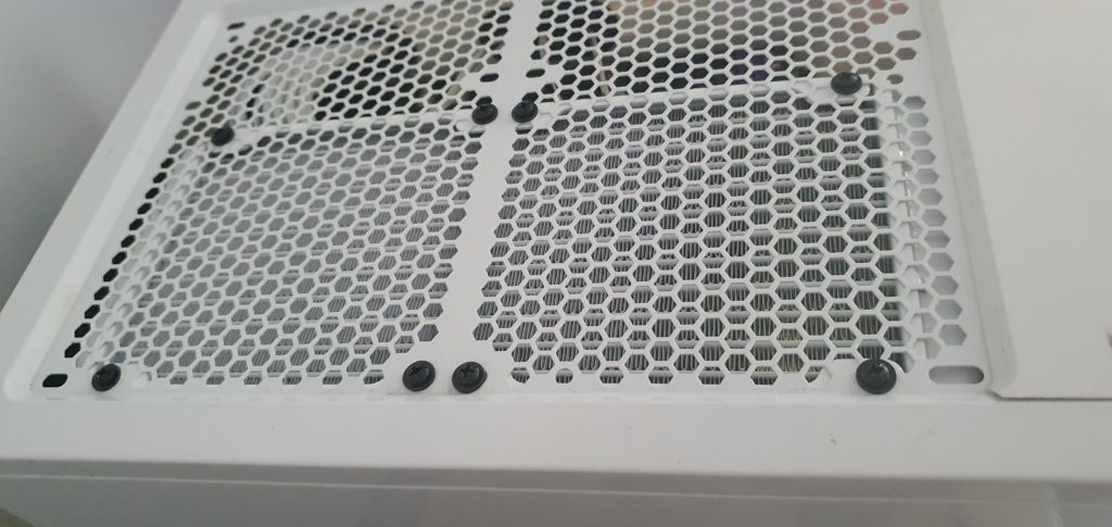
Fitting the radiator
This is probably the most awkward part of the installation as it’s the biggest piece to fit. Give the assembled radiator a final eyeball and consider cable and pipe management before fitting it (this step should have been done when fitting the fans). Remove any vent covers which would obstruct airflow (if you have any) and ensure there are no obstructions such as the EPS 4/8 pin CPU cables if top mounting it, then screw the radiator down using the 8 short black screws provided, be sure to use washers here also (thankfully these are illustrated in the manual). Personally, I mount the two center screws but not quite tight, then a pair of diagonally opposite screws, then the other diagonally opposite, then the remaining two center screws so that it all aligns nicely and can be adjusted if screw holes don’t quite align perfectly. Once all the screws are in I’ll tighten them up following a similar pattern. If it’s a particularly tight case sometimes it’s beneficial to feed cables through as you’re aligning the radiator to save effort with cable management.
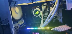
Once done it should look something like the below image for a top mount setup.
Once the radiator is in I find it’s good to tuck the cables (if you didn’t already in the last step) through their appropriate routing holes so that you’ve got a nice clean work area for installing the cold plate.
Install the backplate as pictured below, note how the gap rectangular gap of the cooler’s backplate is aligned with the socket’s backplate. For my LGA-1200 mounting the threads were in their innermost position, the manual instructed that I fix the backplate to the standoffs which have the same sized thread at both ends. Please verify within the manual you should use for your particular socket.
Once the backplate is fixed in place remove the plastic cap from the cold plate and carefully fit it on the standoffs, tighten the AIO in place using the provided thumb-screws. I generally tighten them in a 3 stage process first loosely, then light pressure, then desired pressure tightening opposing corners alternating each stage (so top left, bottom right, bottom left, top right the first time, then top right, bottom left, top left, bottom right the second and so on). You want quite a firm fit but don’t overtighten it otherwise you may damage your motherboard or CPU, even adequate but not excessive pressure is what we’re aiming for.
Cables
Once you’ve mounted the cold plate securely you’ll want to plug the 4-pin PWM header for the pump into either a pump header or usually the CPU_FAN header if it doesn’t have a pump-specific header. For the radiator fans plug the 4-pin PWM header into whichever fan header you feel best suits. Note which you choose as you’ll no doubt want to customize their fan profiles if you want optimal performance. Plug the ARGB header in ensuring that it’s 5 volts and that the pinout matches your motherboards, the pinout goes Ground (or -), blank, data, +5v. Plug the 9 pin USB to micro-USB cable into the USB header on your motherboard and the micro USB plug into your cold plate if you’ve not already and you should be good to go! I recommend taking the time to run the cables as neatly so that you don’t end up impairing airflow or with a cable in a fan. zip ties, double-sided velcro, or electrical tape are your friends here.
Now it’s fit, what next?

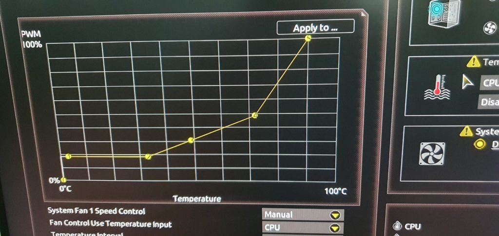
Once it’s installed chances are you’ll want to setup a nice fan profile. Personally, mine is still in the process of being dialed in and currently is setup with the pump running 100%, I intend to alter it so as to not work the pump as hard unless needed. For my radiator fans, I have the following stops set at various CPU temps, the fans are set to PWM control.
- Stop 1 = 18% fan speed @ 1c
- Stop 2 = 18% fan speed @ 32c
- Stop 3 = 30% fan Speed @ 49c
- Stop 4 = 49% fan speed @ 72c
- Stop 5 = 89c at 100% Fan speed
Why it’s configured like this is I find even at 49% fan the CPU rarely exceeds 72c, however, I never want it to hit 90c so I’ve got quite the aggressive ramp from there. Basically, this setup generally allows me less noise than my Prolimatech Megahalems but more than 10c better temps across the board. You’ll probably want to have an experiment with your setup and see where it sits and how loud it is, then adjust your breakpoints as desired. I’ve omitted thermal benchmarks as I do not have sufficient controls in place at this point to provide a reliable comparison.
Final words
The ASUS ROG Strix LC 240 is an excellent choice if you don’t explicitly need LGA-1700 support. I got an excellent deal on this cooler, subjectively the performance of the cooler is great with thermals being substantially improved whilst being sufficiently quiet. The cooler also looks great. The only downsides were the omission of washers being omitted for fan mounting (which is easily remedied) in the manual and the pins not wanting to be removed from the ARGB splitters(also easily remedied) neither of which is a dealbreaker.